
Description
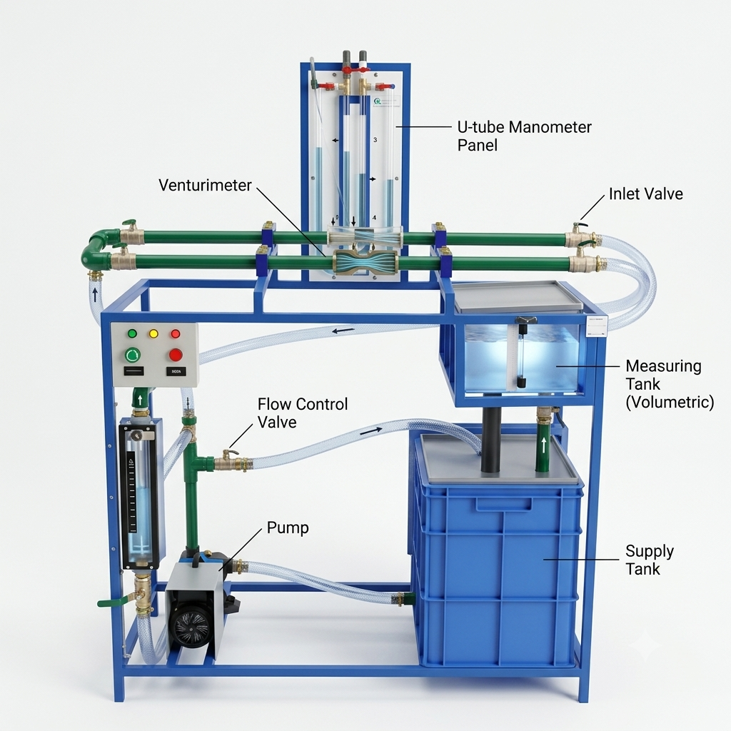
High-precision fluid dynamics educational equipment is engineered and supplied by SV Technocrats India, Pune’s trusted manufacturer of technical laboratory test rigs. The Venturimeter Calibration Apparatus is specifically developed to allow accurate determination of the discharge coefficient ($C_d$), ensuring real-world deviations from theoretical Bernoulli equations are correctly evaluated.
Core System Construction
Precise flow measurement is facilitated through well-integrated structural components:
-
Venturi Assembly: Accelerated flow is achieved in the converging section, minimum pressure is developed within the throat, and velocity is gradually reduced along the diverging section.
-
Instrumentation Taps: Differential pressure ($\Delta P$) is registered using dual pressure taps linked to a U-tube manometer or calibrated gauges.
-
Volumetric Tracking: Actual flow rate ($Q_{\text{actual}}$) is accurately measured using a timed collecting tank or a reference inline flow meter.
Calibration Procedure
-
Installation & Priming: The apparatus is integrated into the piping loop, and leak-free operation is verified across all pressure tap lines.
-
Flow Stabilization: Constant flow is established by the pump system, and flow adjustments are made using control valves.
-
Differential Data Logging: Pressure heads between the inlet and throat are recorded via pressure sensors or manometers.
-
$C_d$ Calculation: Actual flow rate ($Q_{\text{actual}}$) is measured volumetrically using the collecting tank, and the coefficient of discharge ($C_d$) is calculated by comparing $Q_{\text{actual}}$ against theoretical values ($Q_{\text{theoretical}}$).
Key Applications & Advantages
-
Industrial Flow Control: Reliable fluid metering capabilities are provided for pipeline monitoring and industrial process control.
-
Academic & Experimental Research: Theoretical fluid flow models are validated by engineering students through hands-on laboratory experiments.
-
Enhanced Measurement Accuracy: High precision and long-term instrument reliability are maintained through routine calibration routines.
Manufactured in Pune by SV Technocrats India, these units are widely utilized across technical institutions to strengthen fluid mechanics curricula.
Venturimeter Calibration Setups by SV Technocrats India, Pune. Accurately determine the coefficient of discharge in fluid mechanics labs. Enquire now! Buy Fluid Mechanics Laboratory Equipment for Corporate Social Responsibility (CSR) Project. SV Technocrats India set entire Fluid Mechanics Lab on turnkey basis. Enquire now.